![]()
VAG Vehicles with LIN Hazard switch
LinBuster
Hazard LIN Interface
Installation Manual
LB-0002
Version: v2026.01
Introduction
This manual describes the installation of the LinBuster interface
in VAG vehicle with a LIN-Bus connected hazard light switch.
This interface is used to control the hazard light from an external device, like an alarm system.
Functions
- Simple ground switching input signal.
Blinks as long as input wire is grounded. - Retains full vehicle switch function.
- Works in all vehicle ignition modes.
- Sleep mode with ultra-low power consumption (approx. 50 µA / 0.05 mA).
Installation
The interface connects to the LIN-bus wire,
that connects the hazard light switch to the BCM.
The connection can be made on the side of the BCM or at the switch.
Consult your alarm supplier, or vehicle technical documentation for more specific instructions.
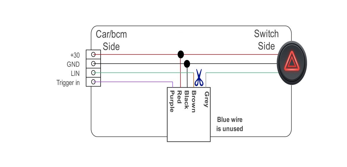
- Find the +30 (permanent 12v) and ground wire, that go to the switch.
- Add the Black and red wire to these wires
- Wait 5 minutes for the vehicle to go into sleep mode.
- Cut the LIN wire that goes to the switch.
- Connect the BCM/CAR side of the cut LIN wire to the grey interface wire.
- Connect the SWITCH side of the cut LIN wire to the brown interface wire.
- Connect the ALARM output to the purple interface wire.
| Interface | Car connection |
|---|---|
| Red | +30 (12V) |
| Black | GND |
| Brown | LIN-Bus (Switch side) |
| Grey | LIN-Bus (BCM side) |
| Purple | Trigger input from alarm |
Status LED
The interface has a small status led, behind the white shrink tube.
The blinking pattern indicates the status.
| Blink | Status |
|---|---|
| 10 fast blinks | Entering sleep mode |
| ON | Not initialized, no data reception |
| ON with 1 off blink | Receiving data, trying to detect car model |
| ON with 2 off blinks | Car model detected, analysing communication pattern |
| 1 fast blink | Normal operation, no LIN data received |
| 2 fast blinks | Normal operation, LIN data received |
| 1 long blink | trigger change detected *1 |
*1 Only during normal operation, during init the trigger input is not active
Coding
No coding is required.
Testing
First let the vehicle go into sleep mode for 5 minutes before testing the interface.
There is an encryption code exchange when the bus starts up, which may have been disrupted during installation.
You can test the system by manually grounding the purple input wire.
The indicators should flash for as long as you hold it to ground.
Also check that the hazard lights work correctly with the original switch.
Diagnosis
If it does not work, follow these steps.
- Lock the vehicle for 5 minutes so the LIN bus goes into sleep mode.
- Turn the ignition on, wait 10 seconds, and look at the LED under the white heat-shrink tube.
- Use the table below to check the interface status.
LED is off
Reset the LinBuster by following these steps:
- Disconnect the red 12 V wire.
- Briefly connect it to ground.
- Reconnect the red wire.
After the reset there are two possibilities:
- The LED turns on briefly and then flashes quickly
No LIN bus was detected. The module then goes into sleep mode.
Check the LIN connection and the wiring. - The LED remains off
Check that the reset was performed correctly.
If the LED remains off, check the supply voltage and ground.
If the voltage is correct, the module may be defective.
LED is on with one short interruption
The LIN bus is recognized, but the vehicle data is not.
This usually means that the vehicle or version does not match the expected protocol.
Contact your supplier for further support.
LED flashes slowly for 4 seconds and then very quickly for 1 second
There is data on the input, but it is not recognized as LIN bus.
Check:
- that the brown and grey wires have not been swapped
- that the correct LIN bus wire is connected.
(check whether the hazard-light switch no longer works correctly)
If this LED status remains, contact your supplier.
LED flashes constantly very quickly and weakly
The 12 V supply is missing; the module is now running on leakage current from the LIN bus.
Check and restore the power supply.
LED flashes a slow double blink, repeating continuously
The LIN bus has been recognized correctly.
Now test the output by briefly grounding the purple wire. There are then two possibilities:
- The LED starts flashing quickly, but the hazard lights do not switch on
Check if the hazard switch is working correctly.- Yes, make sure you are using the correct LIN bus wire.
Or the protocol differs. Contact your supplier.
- No, the switch and bcm could be out of sync. let the car enter sleep mode about 3 times (5 minutes ign off), then test again.
- Yes, make sure you are using the correct LIN bus wire.
- The LED continues flashing a slow double blink
Check whether the purple control wire is actually being pulled to ground.